electric motor terminal box location Typically a hex key (Al-len wrench) is all that is needed. Also, this connection can be used where the motor is terminated on a bus bar in the terminal box (see Figure 2). The disadvantage is . We are a sheet metal company specializing in the fabrication and installation of commercial and residential ductwork and sheet metal products located in Winnipeg. Our team is dedicated to providing high-quality custom metal fabrication and excellent customer service.
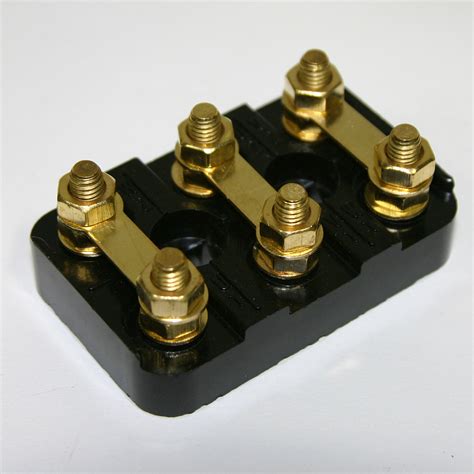
0 · terminal blocks for electric motors
1 · terminal block km6 45x70mm
2 · replacement motor terminal box
3 · motor terminal box catalogue
4 · motor terminal block size chart
5 · motor terminal block catalogue
6 · 3 phase motor terminal box
7 · 3 phase motor terminal block
Starting in 2007 (NNBS) there is no accessory wire to the radio, it is woken up over the computer data lines. To install an aftermarket HU you either need a module, which will also keep your chimes working, or you need to find an accessory source elsewhere.
NOTE: For all NEMA mounting configurations, refer to NEMA MG 1-2009. NEMA Mounting Arrangements BEC-402
The standard IEC mounting position places the junction box on the top of the motor, known as the IM B3 mounting position in IEC frame (or F3 in NEMA frames). On the other hand, the NEMA standard mounting position is referred .Typically a hex key (Al-len wrench) is all that is needed. Also, this connection can be used where the motor is terminated on a bus bar in the terminal box (see Figure 2). The disadvantage is .In motor mounting position B8 (= M3), T is at the bottom. The position of the cable entry can be selected as well. The positions are "X" (= standard position), "1", "2" or "3" ( → Figure 86). . After you've verified that the supply voltage requirements are correct, you then can make the motor terminal connections. Stator winding .
Here we will discuss some of these procedures and outline a few of the advantages and disadvantages of each. We will not consider the starting method or internal connection of the motor, but only the methods used to connect the .The Conduit Box can be located on either side of the frame. F-1 = Conduit box on right-hand side of frame when facing “front” of motor. F-2 = Conduit box on left-hand side of frame when facing “front” of motor.

terminal blocks for electric motors
These instructions must be followed to ensure safe and proper installation, operation and maintenance of the motor. They should be brought to the attention of anyone who installs, .Terminal Boxes NEMA standard location is on left hand side facing output shaft (F1) Optional positions on right hand side (F2) and on top (F0) Flying leads require extra space to connect .Here we will discuss some of these procedures and outline a few of the advantages and disadvantages of each. We will not consider the starting method or internal connection of the motor, but only the methods used to connect the .
NOTE: For all NEMA mounting configurations, refer to NEMA MG 1-2009. NEMA Mounting Arrangements BEC-402The standard IEC mounting position places the junction box on the top of the motor, known as the IM B3 mounting position in IEC frame (or F3 in NEMA frames). On the other hand, the NEMA standard mounting position is referred to as F1, with the junction/conduit box located on the left side of the motor facing the output shaft.Typically a hex key (Al-len wrench) is all that is needed. Also, this connection can be used where the motor is terminated on a bus bar in the terminal box (see Figure 2). The disadvantage is that the secureness of the connection relies on the tightness .In motor mounting position B8 (= M3), T is at the bottom. The position of the cable entry can be selected as well. The positions are "X" (= standard position), "1", "2" or "3" ( → Figure 86). Unless indicated otherwise, you will receive the terminal box type 0° (R) with cable entry "X".
After you've verified that the supply voltage requirements are correct, you then can make the motor terminal connections. Stator winding connections should be made as shown on the nameplate connection diagram or in accordance with the wiring diagram attached to the inside of the conduit box cover.
Here we will discuss some of these procedures and outline a few of the advantages and disadvantages of each. We will not consider the starting method or internal connection of the motor, but only the methods used to connect the motor leads to incoming power. Topics covered include: Types of terminations; Insulating the joints; Medium voltage .The Conduit Box can be located on either side of the frame. F-1 = Conduit box on right-hand side of frame when facing “front” of motor. F-2 = Conduit box on left-hand side of frame when facing “front” of motor.These instructions must be followed to ensure safe and proper installation, operation and maintenance of the motor. They should be brought to the attention of anyone who installs, operates or maintains the motor or associated equipment.Terminal Boxes NEMA standard location is on left hand side facing output shaft (F1) Optional positions on right hand side (F2) and on top (F0) Flying leads require extra space to connect and contain inside IEC standard is on top Optional locations on either side – left (F1) or right (F2) Terminal box can generally be rotated 4 x 90 degrees

terminal block km6 45x70mm
Junction boxes protect electrical wires from damage, prevent shocks, and stop sparks from igniting flammable material nearby. To install one, you’ll need to strip the ends off all the wires that will be in the box. To complete the electrical circuit, tie together the same-colored wires and hold them in place with wire nuts.
electric motor terminal box location|replacement motor terminal box