cervelo p5 di2 junction box Apply a light coat of carbon assembly 300mm compound to chevron and rear surfaces SM-JC41 4-Port E-Wire of the Riser Post Clamp, and install at rear Junction Box of Riser Post ensuring . This video is the first installment of a two part series showing us constructing an elevated deer hunting blind, using material milled on our Woodland Mills sawmill. It also showcases our LS.
0 · cervelo soloist s5 manual
1 · cervelo s5 disc manual
2 · cervelo p5 wiring diagram
3 · cervelo p5 troubleshooting
4 · cervelo p5 manual
5 · cervelo p5 grommet manual
6 · cervelo p5 battery mount
7 · cervelo manual pdf
The pigtail method transfers the connection point from the receptacle to a wire nut. So instead of the feed-through current going through the receptacle, it goes through the wire nut. Which junction is better?
• Slide on the heat shrink tubing and connect the E-wire to the color matched port on the Di2 Junction Box (Figure 10). • Install the rubber Di2 grommet supplied with the frame, onto the .
These manuals contain important safety, performance and service information. Please take the time to read and understand the information before your first ride. In the case of a conflict .
cervelo soloist s5 manual
cervelo s5 disc manual
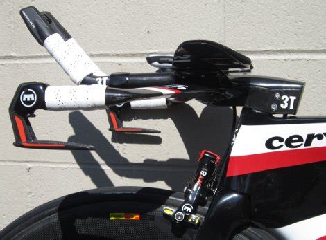
ELECTRIC WIRE ROUTING It is recommended that electric cabling and junction points be installed after the brake hose has been installed. These routing illustrations are intended as a .• Slide on the heat shrink tubing and connect the E-wire to the color matched port on the Di2 Junction Box (Figure 10). • Install the rubber Di2 grommet supplied with the frame, onto the .Apply a light coat of carbon assembly 300mm compound to chevron and rear surfaces SM-JC41 4-Port E-Wire of the Riser Post Clamp, and install at rear Junction Box of Riser Post ensuring . To test your work, just crack open the cockpit to access the 5-port junction box standard on the P5. There are two open ports on the box. Just plug the hack in. No need to fish the wires through the base bar to test your work.
I changed my stem to a Profile Design Aeria Ultimate - I hides the Di2 junction box and has front hydration that mounts to it. Profile Design ATTK for nutrition. I also have, and highly recommend the aero tool box from Radsport Ibert - . How to install the EX10 tilt-adjustable aerobar without having to hide the Shimano Di2 junction box in a bike's bento box. This is the cleanest and most versatile way way to setup your P5 Disc .You need to click the button on the junction box to change in all likelihood. YouTube it if your not sure. Once the shifting mode is set correctly just by shifting up it will eventually go into the little . A void within the stem hides the Di2 junction box and wires, plus hoses for the Magura RT8 hydraulic callipers. Their delta shape matches that of the fork crown, and a two .
K+,999.99,999.99
,999.99• Slide on the heat shrink tubing and connect the E-wire to the color matched port on the Di2 Junction Box (Figure 10). • Install the rubber Di2 grommet supplied with the frame, onto the cable exit hole on the drive side chain stay (Figure 11).These manuals contain important safety, performance and service information. Please take the time to read and understand the information before your first ride. In the case of a conflict between the instructions in our manuals and information provided by a component manufacturer, always follow the component manufacturer’s instructions.
ELECTRIC WIRE ROUTING It is recommended that electric cabling and junction points be installed after the brake hose has been installed. These routing illustrations are intended as a supplement to the manufacturer’s 1400 mm installation instructions only.• Slide on the heat shrink tubing and connect the E-wire to the color matched port on the Di2 Junction Box (Figure 10). • Install the rubber Di2 grommet supplied with the frame, onto the cable exit hole on the drive side chain stay (Figure 11).Apply a light coat of carbon assembly 300mm compound to chevron and rear surfaces SM-JC41 4-Port E-Wire of the Riser Post Clamp, and install at rear Junction Box of Riser Post ensuring that the clamp is fully inserted, and no chevrons are visible. To test your work, just crack open the cockpit to access the 5-port junction box standard on the P5. There are two open ports on the box. Just plug the hack in. No need to fish the wires through the base bar to test your work.
cervelo p5 wiring diagram
I changed my stem to a Profile Design Aeria Ultimate - I hides the Di2 junction box and has front hydration that mounts to it. Profile Design ATTK for nutrition. I also have, and highly recommend the aero tool box from Radsport Ibert - https://shop.radsport-ibert.de/de/aerotoolbox/cervelo/105/atb-cervelo-p5/p-series-disc?c=34 How to install the EX10 tilt-adjustable aerobar without having to hide the Shimano Di2 junction box in a bike's bento box. This is the cleanest and most versatile way way to setup your P5 Disc . You need to click the button on the junction box to change in all likelihood. YouTube it if your not sure. Once the shifting mode is set correctly just by shifting up it will eventually go into the little ring in the front. A void within the stem hides the Di2 junction box and wires, plus hoses for the Magura RT8 hydraulic callipers. Their delta shape matches that of the fork crown, and a two-part aero cover.
• Slide on the heat shrink tubing and connect the E-wire to the color matched port on the Di2 Junction Box (Figure 10). • Install the rubber Di2 grommet supplied with the frame, onto the cable exit hole on the drive side chain stay (Figure 11).These manuals contain important safety, performance and service information. Please take the time to read and understand the information before your first ride. In the case of a conflict between the instructions in our manuals and information provided by a component manufacturer, always follow the component manufacturer’s instructions.
ELECTRIC WIRE ROUTING It is recommended that electric cabling and junction points be installed after the brake hose has been installed. These routing illustrations are intended as a supplement to the manufacturer’s 1400 mm installation instructions only.
• Slide on the heat shrink tubing and connect the E-wire to the color matched port on the Di2 Junction Box (Figure 10). • Install the rubber Di2 grommet supplied with the frame, onto the cable exit hole on the drive side chain stay (Figure 11).Apply a light coat of carbon assembly 300mm compound to chevron and rear surfaces SM-JC41 4-Port E-Wire of the Riser Post Clamp, and install at rear Junction Box of Riser Post ensuring that the clamp is fully inserted, and no chevrons are visible. To test your work, just crack open the cockpit to access the 5-port junction box standard on the P5. There are two open ports on the box. Just plug the hack in. No need to fish the wires through the base bar to test your work. I changed my stem to a Profile Design Aeria Ultimate - I hides the Di2 junction box and has front hydration that mounts to it. Profile Design ATTK for nutrition. I also have, and highly recommend the aero tool box from Radsport Ibert - https://shop.radsport-ibert.de/de/aerotoolbox/cervelo/105/atb-cervelo-p5/p-series-disc?c=34


How to install the EX10 tilt-adjustable aerobar without having to hide the Shimano Di2 junction box in a bike's bento box. This is the cleanest and most versatile way way to setup your P5 Disc . You need to click the button on the junction box to change in all likelihood. YouTube it if your not sure. Once the shifting mode is set correctly just by shifting up it will eventually go into the little ring in the front.
cervelo p5 troubleshooting

cervelo p5 manual
cervelo p5 grommet manual
cervelo p5 battery mount
Sheet metal bending refers to deforming the flat metal sheet into a specific angle or curvature. It does not change the thickness of the sheet. Instead, the plastic (permanent) deformation is responsible for the formation of the final shape.
cervelo p5 di2 junction box|cervelo p5 manual