solidworks sheet metal part The Convert to Sheet Metal command lets you specify the thickness, bends, and . Edit: If you or anyone genuinely wanted to know which exact levels contain the casually called "BS hidden boxes", it's the following ones: A Real Grind, Truck Stopped, Potion Commotion, Off-Balance, Run it Bayou, No Dillo Dallying, Blast to the Past, Fossil Fueled, Crash Landed, Rush Hour, and Toxic Tunnels.
0 · solidworks sheet metal pdf
1 · solidworks sheet metal examples
2 · solidworks sheet metal drawing pdf
3 · solidworks sheet metal download
4 · solidworks sheet metal basics
5 · sheet metal modeling in solidworks
6 · sheet metal in solidworks 2021
7 · sheet metal 3d sketch solidworks
So many have boxes made of sheet metal, with metal stakes attached to the bottom, and driven into the ground either over the body of the grave or behind the headstone. Candles can be lit in.
You can design a sheet metal part on its own without any references to the parts it will enclose, you can design the part in the context of an assembly that contains the enclosed components, .

sheet metal workers pension plan of northern california
Properties specific to sheet metal parts are calculated and displayed in the Cut-List .When designing sheet metal parts, the order preference for use of feature tools .The Convert to Sheet Metal command lets you specify the thickness, bends, and .

solidworks sheet metal pdf
Properties specific to sheet metal parts are calculated and displayed in the Cut-List Properties dialog box. When you assign a custom material to a sheet metal part, you can link the sheet .When designing sheet metal parts, the order preference for use of feature tools are as follows: 1. Use sheet metal features such as base-flanges, edge-flanges, miter flanges, etc. 2. Use the .
SOLIDWORKS 3D allows you to quickly create sheet metal part designs using a simple design process, saving you time and development costs, thanks to specific sheet metal features. We can use these features to create . In this lesson, you create the sheet metal part. This lesson demonstrates: 1.Creating a base flange 2.Adding a miter flange 3.Mirroring the part and creating. By the end of this tutorial, you'll be well-equipped to design your own sheet metal components confidently in SolidWorks. Music: Inspire by Wavecont https://protunes.net Video Link: •. How to Use SolidWorks Base Flange | SolidWorks SheetMetal Tutorial #1. Base Flange is first and basic step used to start sheet metal model. It is applicable one per part file. You can create single open, single closed or .
solidworks sheet metal examples
solidworks sheet metal drawing pdf
There are multiple methods for making sheet metal parts in Solidworks using the Sheet Metal tab. In this article, we will look at using the Sketched Bend feature and also the Edge Flange feature. Both of these .

How to Prepare Rolled Sheet Metal Parts in SolidWorks. Let’s walk through the steps necessary to flatten a rolled sheet metal part in Solidworks to prepare it for laser cutting. Step 1: Use “Cut-Extrude” to make a parting line in .
The Convert to Sheet Metal command lets you specify the thickness, bends, and rips necessary to convert a solid part to a sheet metal part.
If you cannot insert an axis, then the model is not an exact cylinder and cannot be unfolded. However, sheet metal parts created with the Lofted Bends feature avoid this limitation and unfold appropriately. . Version: SOLIDWORKS 2018 SP05 To disable help from within SOLIDWORKS and use local help instead, click Help > Use SOLIDWORKS .The sheet metal-specific features make it easier and faster to create a sheet metal part than designing a part, then converting it to sheet metal. SOLIDWORKS includes sheet metal-specific features so you can create a part as sheet metal without having to convert it to sheet metal.Under Sheet Metal Parameters: Select a face as the fixed face for the sheet metal part. Set the sheet thickness and default bend radius. Select Keep body if you want to keep the solid body to use in another Convert to Sheet Metal feature. When cleared, the body is consumed by the Convert to Sheet Metal feature. SOLIDWORKS 3D allows you to quickly create sheet metal part designs using a simple design process, saving you time and development costs, thanks to specific sheet metal features. We can use these features to create sheet metal designs with several different methods.
You can create a multibody sheet metal part using any command that creates multiple bodies from a single body. Use these commands on the Features toolbar to split a sheet metal part into multiple bodies: . SOLIDWORKS welcomes your feedback concerning the presentation, accuracy, and thoroughness of the documentation. .Adding Walls to Sheet Metal Parts. Creating Elliptical Bends. You can sketch an ellipse and a create sheet metal part that has elliptical bends. Drawings of Sheet Metal Parts. When you create a drawing of your sheet metal part, a flat pattern is automatically created. Drawings of sheet metal parts can also contain views of the bent sheet metal .
Adding Walls to Sheet Metal Parts. Creating Elliptical Bends. You can sketch an ellipse and a create sheet metal part that has elliptical bends. Drawings of Sheet Metal Parts. When you create a drawing of your sheet metal part, a flat pattern is automatically created. Drawings of sheet metal parts can also contain views of the bent sheet metal .If creating a sheet metal part with one or more conical faces, you must select K-Factor as the type of bend allowance. If you selected K-Factor, Bend Allowance, . SOLIDWORKS welcomes your feedback concerning the presentation, accuracy, and thoroughness of the documentation. Use the form below to send your comments and suggestions about this .
Adding Walls to Sheet Metal Parts. Creating Elliptical Bends. You can sketch an ellipse and a create sheet metal part that has elliptical bends. Drawings of Sheet Metal Parts. When you create a drawing of your sheet metal part, a flat pattern is automatically created. Drawings of sheet metal parts can also contain views of the bent sheet metal .The bounding box is represented by a sketch when you flatten the sheet metal part and is located in the FeatureManager design tree under Flat-Pattern. You can also create a bounding box for any cut list item in a cut list, independent of the type of solid or sheet metal bodies in the cut list item. Example of bounding box sketch in a flat pattern:Search 'Mirroring Sheet Metal Parts' in the SOLIDWORKS Knowledge Base. Provide feedback on this topic. SOLIDWORKS welcomes your feedback concerning the presentation, accuracy, and thoroughness of the documentation. Use the form below to send your comments and suggestions about this topic directly to our documentation team. The documentation .
Adding Walls to Sheet Metal Parts. Creating Elliptical Bends. You can sketch an ellipse and a create sheet metal part that has elliptical bends. Drawings of Sheet Metal Parts. When you create a drawing of your sheet metal part, a flat pattern is automatically created. Drawings of sheet metal parts can also contain views of the bent sheet metal .
solidworks sheet metal download
Open the part to be split. Create a sketch to be used to split the part. Select Split (Features toolbar).; In the PropertyManager, under Trim Tools, select the sketch.; Click Cut Part.; Under Resulting Bodies, under , specify the bodies for the split operation.; Optionally, click the callout for each body and save it using the Save As dialog box.. The names appear in the .Using Sheet Metal Tools. Using Forming Tools with Sheet Metal. Forming tools are parts that act as dies that bend, stretch, or otherwise form sheet metal to create form features such as louvers, lances, flanges, and ribs. Sheet Metal Parts. Multibody Sheet Metal Parts. SOLIDWORKS multibody part functionality lets you work with several bodies in .Using Forming Tools with Sheet Metal. Forming tools are parts that act as dies that bend, stretch, or otherwise form sheet metal to create form features such as louvers, lances, flanges, and ribs. Sheet Metal Parts. Multibody Sheet Metal Parts. SOLIDWORKS multibody part functionality lets you work with several bodies in one part to create .You can create a multibody sheet metal part using any command that creates multiple bodies from a single body. Use these commands on the Features toolbar to split a sheet metal part into multiple bodies: . SOLIDWORKS welcomes .
You cannot add walls to cylindrical or conical faces on sheet metal parts. To add a wall to a sheet metal part: Open a sketch on the face of a sheet metal part where the new wall will be attached. . SOLIDWORKS welcomes your feedback concerning the presentation, accuracy, and thoroughness of the documentation. .
You can create a multibody sheet metal part from multiple sheet metal bodies or a combination of sheet metal bodies and and other bodies such as weldments. . SOLIDWORKS welcomes your feedback concerning the presentation, accuracy, and thoroughness of the documentation. Use the form below to send your comments and suggestions about this topic . In this lesson, you create the sheet metal part. This lesson demonstrates: 1.Creating a base flange 2.Adding a miter flange 3.Mirroring the part and creating. we will learn sheet metal basic features like Base Flange,Edge Flange ,Sketched bend and Extruded Cut in Solidworks sheet metal.1)Solidworks tutorial for Beg.
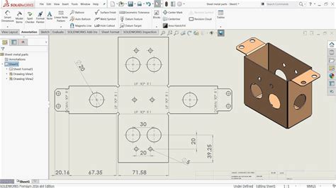
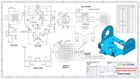
Search 'Mirroring Sheet Metal Parts' in the SOLIDWORKS Knowledge Base. Provide feedback on this topic. SOLIDWORKS welcomes your feedback concerning the presentation, accuracy, and thoroughness of the documentation. Use the form below to send your comments and suggestions about this topic directly to our documentation team. The documentation .You can convert any imported sheet metal type part to a SOLIDWORKS sheet metal part. The imported part must be a constant thickness. If the part you are converting has a formed feature, the formed feature is deleted. You can reapply the feature after the conversion.When you create a drawing of your sheet metal part, a flat pattern is automatically created. Drawings of sheet metal parts can also contain views of the bent sheet metal part. . SOLIDWORKS welcomes your feedback concerning the presentation, accuracy, and thoroughness of the documentation. Use the form below to send your comments and .Now create a drawing of the sheet metal part. Start with an isometric view of the folded model, and then add a view of the unfolded model. Click Options (Standard toolbar).; On the System Options tab, click Drawings > Display Style.; Under Tangent edges, select Visible, and click OK.; Click Make Drawing from Part/Assembly (Standard toolbar) or File > Make Drawing from Part, .
There are multiple methods for making sheet metal parts in Solidworks using the Sheet Metal tab. In this article, we will look at using the Sketched Bend feature and also the Edge Flange feature. Both of these features are used to create bends starting from a flat piece of metal.When you create a drawing of your sheet metal part, a flat pattern is automatically created. Drawings of sheet metal parts can also contain views of the bent sheet metal part. . SOLIDWORKS welcomes your feedback concerning the presentation, accuracy, and thoroughness of the documentation. Use the form below to send your comments and .Search 'Mirroring Sheet Metal Parts' in the SOLIDWORKS Knowledge Base. Provide feedback on this topic. SOLIDWORKS welcomes your feedback concerning the presentation, accuracy, and thoroughness of the documentation. Use the form below to send your comments and suggestions about this topic directly to our documentation team. The documentation .
solidworks sheet metal basics
What is an electrical junction box used for? An electrical junction box is used for several purposes, including: Containing and protecting electrical connections, such as wire splices and wire terminations. Preventing contact with live wires, which reduces the risk of electrical shocks and fires.
solidworks sheet metal part|solidworks sheet metal download