How to calculate bend allowance, K factor and Y coefficient in one click. To calculate the bend allowance, the K factor and the derived coefficient called the Y factor, insert the thickness and initial length of the sheet into the cells on the left.After bending the sheet, insert the inner radius, and flanges A and B. Bending angle is 90°.
So, now you have a formula for the BA—but where’s the k-factor? It’s hiding in that 0.0078 value, which is π/180 × k-factor. To arrive at 0.0078, the equation uses a k-factor of 0.4468, a commonly used factor that’s the default for many CAD systems. In order to simplify the definition of the sheet metal neutral layer and make it applicable to all materials, the concept of the K-factor was introduced. The definition of the K-factor is: it is the ratio of the thickness of the sheet metal’s neutral layer to the overall thickness of the sheet metal part material.The K-Factor is a geometric constant used in sheet metal fabrication that relates the position of the neutral axis to the material’s thickness. This factor helps in determining how much the metal will stretch during bending. . The K-Factor is calculated using the formula: K-Factor = (t / 2) / (t + r), where ‘t’ is the material thickness .Y factor and K factor represent part constants used in formulas to calculate the developed length of flat sheet metal required to make a bend of a specific radius and angle in a design. Y factor and K factor are defined by the location of the sheet metal .
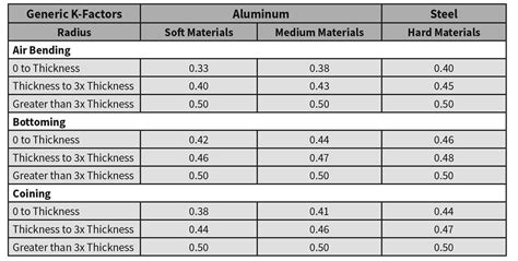
The SkyCiv K-Factor for Sheet Metal is a free tool designed to help engineers and fabricators understand the effects of their sheet metal bending designs. . Plug these values directly into the above formula, note in the . K-Factor is the ratio of the neutral axis to the material thickness. Many designers reference a chart like this or use test pieces to calculate the K-Factor for specific projects. SOLIDWORKS defaults to calculating the flat .
What is K-factor? K-factor is a crucial parameter used in sheet metal bending calculations. It represents the location of the neutral axis in a bent sheet metal part. The neutral axis is the theoretical line within the material thickness where neither . The neutral axis is a theoretical place within the sheet metal material thickness that experiences no expansion or compression. . You can do this by running test bends, measuring the results, and extracting the k-factor from the BA formula that incorporates the results you measured. It might be your best option, especially if you’re . Figure 2 illustrates the sheet that is bent with the bend angle of 90 degrees. We will start by calculating the Bend Allowance. From there we can calculate the K-Factor and the Bend Deduction. After bending the sheet we need to do some measurements as shown in Figure 2.
To change the K-Factor for a sheet metal part, select the root node in the Mechanical Browser and type a value in the K-Factor field. The value must lie in the range [0, 1], since the neutral surface is located inside the sheet metal part. . This value fits the formula exactly: a straight angle in radians roughly equals 1.57 (PI/2). The .From and is defaulted at .5, leading to a K-Factor of approximately .318, which is not a terrible starting place for sheet metal design. The Y and K-Factors affect how the part stretches when transitioning from a flat pattern to a finished piece so it is important to understand their values. The k-factor is fundamental in the press-bending sector and is closely linked to the concept of spring back. It is also known as bend allowance and serves to calculate the sheet metal layout. Knowing the k-factor formula is essential in order to bend any kind of sheet metal correctly; in fact, it varies according to the type of material to be deformed. .K Factor in sheet metal bending is a constant used to calculate sheet metal flat length or Flat-pattern. Mathematically k factor value is equal to the ratio of position of neutral axis and sheet thickness. During sheet metal part bending, the inside bending surface is compressed, whereas the outer surface is stretched.
Of all the mathematical constants in precision sheet metal fabrication, the k-factor stands out. It’s the base value needed to calculate bend allowances (BA) and ultimately the bend deduction (BD). . you can calculate the Y-factor with the following formula: Y-factor = (k-factor × π) / 2. If you do use the Y-factor, you’ll need to make .If R factor is know, this easier formula can be used to calculate the K factor: K factor = inches of thickness / R Factor.K-factor helps to calculate the discharge rate from fire sprinkler heads.K-factor of 4 or 13 is typical and is frequently specified and installed. This has been illustrated in the image given below for better .
For instance, if the distance from the inside radius of the bend to the neutral bend line (D) is 5 mm and the thickness of the sheet metal (T) is 2 mm, the K Factor would be calculated as follows: \[ K = \frac{5}{2} = 2.5 \] Importance and Usage Scenarios. The K Factor is crucial in the field of sheet metal fabrication for several reasons.
Calculation of sheet metal unfolding through 3D modeling software by K-Factor method and its application range. The manual drawing process is low in efficiency. By using a three-dimensional modeling software and the K-factor method, the efficiency of sheet metal unfolding calculation is significantly improved.

k factor sheet metal calculator